 Say hello!
 Off-grid solar wiring diagram explained
Here is a simple step-by-step explanation, written by an electrician, explaining a typical off-grid solar panel electrical system wiring diagram.
Once you have downloaded our free off-grid solar calculator, and filled it in, you will find that your specification has generated your own custom wiring diagram on the second page (spreadsheet) in the Excel workbook.
The first important thing to note is that current flows from left to right across the wiring diagram. The only exception is between the battery and the main busbar where, of course, the current can flow in either direction; in to charge, or out to the electrical load, depending on battery state.
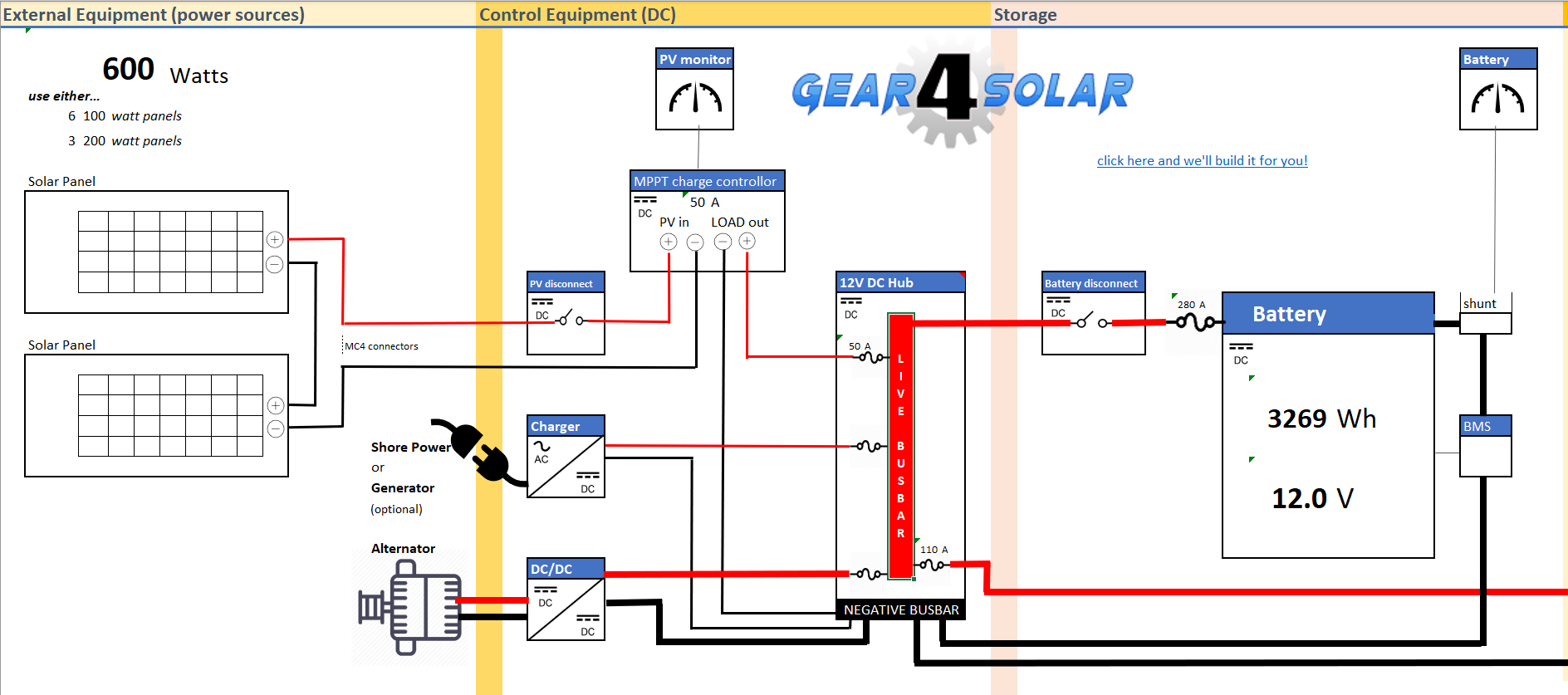
The page is divided into three sections.
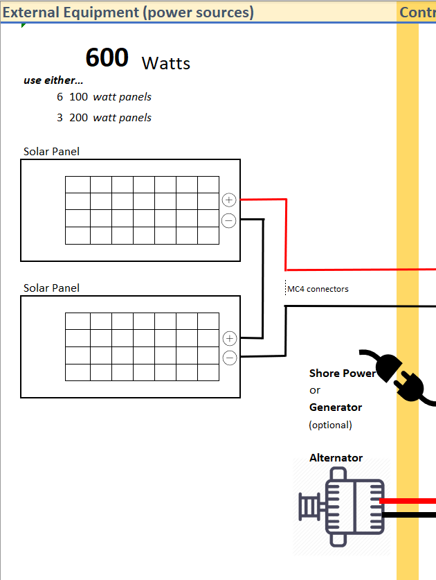
The left-hand section contains the specifications for your solar panels, calculated from page 1 of the spreadsheet dynamically as you entered data. You will see at the top of this section the recommended wattage carried forward.
Below that, you will see suggestions for the panel array. Using this information, you can measure up the space available on top of your van or boat and purchase your panels to suit. If you find you need more panels than available space, you will need to reduce your loads or supplement the system with other sources of energy.
If you want to run several high-powered appliances for any length of time it is wise to have alternative sources. Solar is unpredictable, your solar panels produce less energy on cloudy days.
The other two power source options to charge your batteries are a shore power mains charger connection or a 12 Volt DC vehicle alternator.
Central Section - Control gear
The central section shows the required control equipment inside your power distribution cupboard. It is all DC except for the mains battery charger, which converts incoming mains AC to DC.
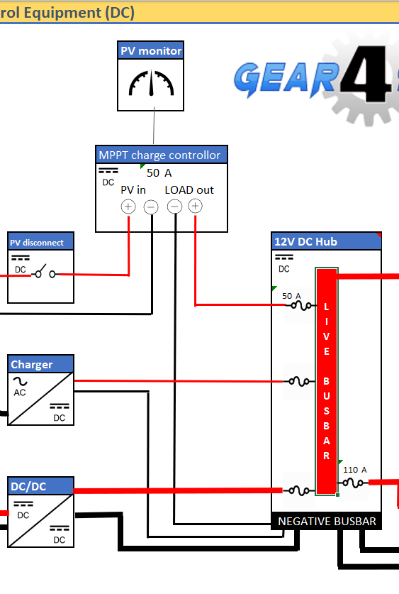
If we follow the line from the solar panels through, we will see it is connected to an MPPT charge controller. This is a device that smooths out the voltage fluctuations (for example as the panels go into and out of shade). It provides a constant current (at a maximum slightly higher than the battery voltage). The MPPT is a unidirectional device. It does not allow current to flow from the battery back into the panels!
The next stage is the main busbar, a central DC connection point. Here you will see fuses that protect your wires from over current. The values of these fuses are auto generated from your data on page one.
- The left-hand side of the busbar shows energy in from your sources.
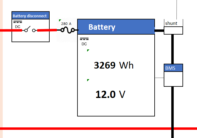
- The right-hand side of the busbar shows the battery connection. When the battery is charged current flows to the busbar.
When the battery voltage is low current flows into it. Electricity always follows the line of least resistance.
Cable sizes are not calculated because that would require knowing the length of run, though we do plan to add this functionality in the future so be sure to subscribe and ring the bell on YouTube to be notified.
In the meantime, there is a look-up table you can use to calculate cable sizes yourself on the spreadsheet downloadable from gear4solar.com.
Third section - ancillaries and loads
You will now need to scroll horizontally across the page to reveal the rest of the circuit.
Staying in the equipment cupboard, we can see some ancillary equipment connected to the negative side of the battery. There is a BMS (battery management system) which keeps your battery cells balanced, and a shunt, which allows a battery monitor to be connected.
Quite often much of the equipment on the equipment panel is smart; it can connect via Bluetooth to an app on your phone.
The rest of the circuit, with current still moving from right to left, comprises distribution and loads, starting with the inverter.
The auto calculated inverter size for your AC load is displayed.
An inverter's main purpose is to convert your DC to AC (it increases the voltage too). This is the opposite of the battery charger we saw earlier in the circuit - it steps down AC mains voltage to 12V DC. Many appliances are fussy about the quality of AC current, they can even be damaged, so an inverter needs to mimic what you get from your grid supply, so your inverter must be a pure sine wave inverter.
We do not show much between this stage and the loads. There will inevitably be division into circuits with attendant over-current protection as well as switches for isolation. Also not shown are DC circuits fed from the busbar.
One caveat - this calculator is provided 'as is' and its advice should be confirmed by a qualified professional or other competent person.
Please leave comments on our YouTube page or contact us here